Prehistoric Canals (Dykes) – Great Chesters Aqueduct (The Vallum Pt. 4)
Promotional Video – Ancient Prehistoric Canals (Dykes) – The Vallum (Great Chesters Aqueduct)
Extract From Book……………………… Ancient Prehistoric Canals (Dykes) – The Vallum
Traditional archaeologists and archaeological establishments like English Heritage suggest that:
The Vallum is a massive earthwork constructed shortly after Hadrian’s Wall itself and lying just south of it. Many visitors confuse the Vallum with Hadrian’s Wall itself because it’s such an obvious and impressive feature in the landscape.
In fact, the Vallum is made up of several different elements – a ditch around 6 metres wide and 3 metres deep; two mounds either side of the ditch about 6 metres wide and 2 metres high and set back from the ditch by around 9 metres; and often a third mound on the southern edge of the ditch. The whole complex is around 36 metres across. Usually, the Vallum runs close behind the Wall but in the rocky and hilly central section the Vallum lies up to 700 metres from the Wall.
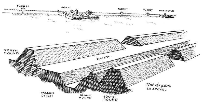
Crossing points seem to have been located south of each of the forts along Hadrian’s Wall and near several of the milecastles. Evidence from the excavated Vallum crossing at Benwell in Newcastle shows these crossing points had impressive monumental gateways.
The Vallum’s purpose is unclear. Many archaeologists think it marks the southern boundary of a military zone with the Wall itself forming the northern boundary. This would have helped protect the rear of the Wall and its associated military installations, with civilian access being closely controlled. The gateway at Benwell supports this idea. The numerous gateways along the Wall at forts and milecastles suggest that the frontier was intended as much to control movement as to provide a defensive line. Traders would have moved goods across the frontier but their movements would have been controlled and their goods taxed.
Relatively soon after it was constructed, some 20 to 30 years perhaps, the Vallum seems to have lost its function – the mounds were cut through and the ditch filled in at fairly regular intervals. It was out of use by the time the forts along the Wall were re-commissioned in the late second century AD following the return of the garrison from the Antonine Wall.
Sadly, these ideas that have been constructed over the last 200 years are somewhat questionable. Within the book we look at associated aspects of this area like Military Way which was supposed to be constructed to patrol the so-called ‘Military Zone’ – to find that:
That over 50% of Military Way does not exist as a separate road, as described by archaeologists. Instead, the perceived road is fragmented and only becomes ‘alive’ as an independent road when the Vallum separates from the wall at any distance.
This might give us a clue to the function of this rough and wonky road, as the stone for the wall would have needed to be delivered by cart if the Vallum canal was not available.
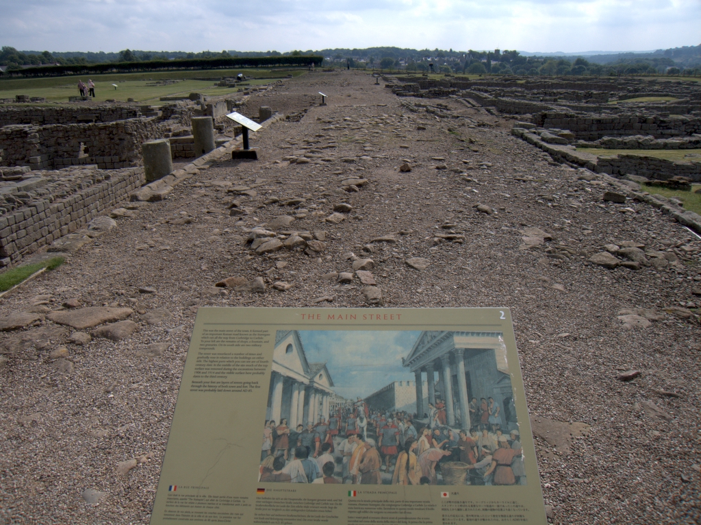
As for the Stanegate that was supposed to connect to the main forts in the area as a ‘defensive shield’ we actual found that it is very little to no evidence of the ‘Stanegate Roman Road’, which (according to the current theory proposed by English Heritage) ‘consolidated as a frontier’ during the late first and early second century AD and helped crystallise Roman tactics and military expectations in the area.
This evidence is compounded when you release that of the 80mile border from coast to coast – Stonegate, at best, covers just 38.1 miles (47%) of the ‘defensive gap’, and hence suggestions of extension over and above the existing line existed (even without support from OS maps). Moreover, the research has shown the ‘raw’ Stanegate road without the ‘hidden’ parts below the B-roads – we are only looking at 20% of the declared road being visible on LiDAR maps.
Stanegate Road (when not part of an existing B-road system) is inconsistent in width and structure -moving from bank track to road with two ditches on each side to a ditch with two banks far from straight and usually starts and ends in ravens.
Most Forts and the Stanegate are not found to connect (with intersecting sub-roads) on only two occasions, and the rest show no connection. Moreover, later ‘temporary’ camps also did not connect with the road – which questions whether (a defence line) was its purpose.
Moreover, this would then question the ‘myth’ of using the Stanegate as a ‘boundary’ for withdrawing troops from Scotland in the first century AD is correct. And whether the River Tyne (which most of these Forts sit upon) was used as a more practical and effective boundary/defence.
This ‘myth buster’ will not surprise many in academia as it has been ‘hinted’ at for some time (but not acted upon it by updating the literature), as we see from Symonds et al.
“The question of whether a road even existed when the fortlets were founded is by default an existential one for the notion that they provided highway protection. But even if the metalled road does post-date the fortlets, a reasonably robust thoroughfare of some form must have existed from at least the mid AD 80s to service Vindolanda. The question is not whether there was a road, but whether it was metalled when the fortlets were founded.” Symonds, M. (2017). Hadrian’s Wall. In Protecting the Roman Empire: Fortlets, Frontiers, and the Quest for Post-Conquest Security (pp. 95-132)
Moreover, even if Stanegate was not built as suggested, it exists in parts, and it looks prehistoric (by design) as it relies heavily on ravens that start and end sections of the Stanegate sections; its sunken structure in parts is unfamiliar to traditional Roman Road design.
As for other famous ‘Roman Features Such as the Great Chesters Aqueduct, again we find not only is the origin questionable but as it located supposedly fully in ‘hostile territory – they its usefulness win conflict would be limited.
It is clear from the LiDAR research that the suspected Roman Aqueduct is not as it seems. This is not the first examination to spread doubt about the scale and origin of this feature in the landscape – MacKay, D. A. (1990). The Great Chesters Aqueduct: A New Survey. Britannia, 21, 285–289. Also shows an incomplete map of this aqueduct.
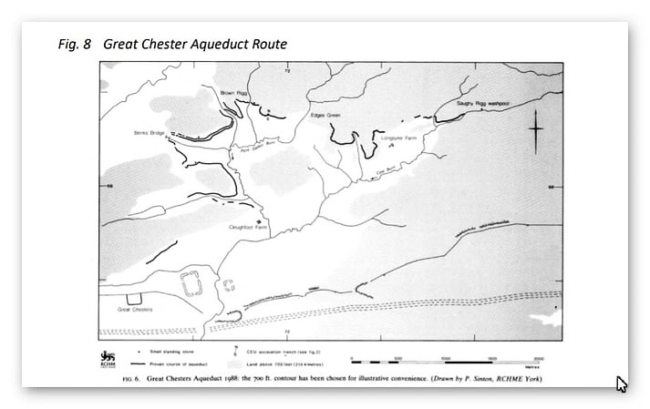
Mackey failed to find in their survey that the Aqueduct changed size, and the path suggested had no identifiable remains of the bridges required to make this Aqueduct work.
Our more detailed findings indicate that the topology of the aqueduct suggests that it would need to go uphill at several points without any powered assistance (like a siphon) and so is mechanically unsound. Our finding has found that the use of ‘Dykes’ in this area and some connecting to this Aqueduct feature is new. We have also shown that closer to the Fort it was supposed to supply, there were closed water sources which could be used and that the Fosse by the Wall was also a water supply.
We conclude that we found a prehistoric watercourse linked to their sophisticated ‘Dyke’ system. I would be bold to suggest that this was used for either agricultural purposes or maybe industrial, seeing the multiple sites of quarries associated and in the region of this feature.
Case Study – The Great Chesters Aqueduct
According to Historic Britain’s scheduling details: “The monument includes the remains of an aqueduct of Roman date, which carried water from Caw Burn westwards to Great Chesters Roman fort. The aqueduct adopts a circuitous route closely following the topography of the landscape. The protected portions of the monument are contained within five separate areas of protection, which stretch over approximately 8.68km of the aqueduct’s length. The aqueduct is preserved as a partial earthwork and in other locations as a cropmark.” – doesn’t tell us much really?
Sadly, It’s all very loose with no excavations, just a few field walkers to verify the aqueduct – if it is an aqueduct, that is.
Great Chesters Roman Aqueduct (NY741688 to NY703668) – according to the book NORTH-EAST HISTORY TOUR
“One of the neatest feats of Roman engineering in the region is one of the least known. It is the 9.5km line of the Roman aqueduct leading into the old fort of Great Chesters from the NE, a little to the north of Haltwhistle.
Only very faint traces of it remain today, but the logistics of the little water supply project are impressive. Basically, when Great Chesters fort was built on the Wall it didn’t have a nearby water supply, so it had to be piped in from the Caw Burn, about 4km to the NE (more specifically, Saughy Rigg Washpool near Fond Tom’s Pool). However, as the engineers had to rely purely on gravity, the path of the aqueduct took a long and curling route through a 9km+ course to pick up every tiny inch of downhill along the way.
The result was a remarkable bendy, twisting affair taking the channel on a constantly downward trajectory at the almost unbelievably gentle gradient of about 1m drop for every 1,000m travelled. And, once more, the flow of water was eased along a simple, unlined water-course about ½ m wide by ¼ m deep, with the occasional small wooden bridge inserted to take it over minor valleys and streams.
The course of the aqueduct is clearly shown on modern-day OS maps (there’s a decent representation here – and scroll down a bit), though it is not so easy to pick out on the ground. Partial earthworks survive, and in other places crop marks provide the circumstantial evidence.“
Sadly, this perception of History is typical due to the misunderstanding of the Landscape in the past and the misconception of ‘Linear History’ – technology growth and sophistication from one century to the next – which strangely, the Roman empire disproves (ask anyone in the Dark Ages who needed to live in Mud Huts with contaminated food and water supplies?
If we now look at modern methods to look at this feature, we see the problem with the assumption that this is a Roman Aqueduct.
The profile of the alleged aqueduct is not this ” gentle gradient of about 1m drops for every 1,000m travelled ” but a haphazard path which would need the aqueduct to defy the laws of gravity in many areas.
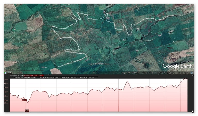
Within this path there are no less than six connections to river valleys. It has been suggested that ‘wooden’ (as no stone has ever been found was used to bridge the gaps!! What has not been explained is the last leg of this epic journey, where the aqueduct goes uphill by 10m in the last 800m of the journey.
Moreover, the Fort has a much closer source of water – in fact, several sources of water, which makes such an aqueduct irrelevant.
If we ‘reverse engineer’ the water sources of fort Aesica we can reveal something quite misunderstood.
Aesica – Wikipedia
Aesica (with the modern name of Great Chesters) was a Roman fort, one and a half miles north of the small town of Haltwhistle in Northumberland, England. It was the ninth fort on Hadrian’s Wall,
Between Vercovicium (Housesteads) to the east and Magnis (Carvoran) to the west. Its purpose was to guard the Caw Gap, where the Haltwhistle Burn crosses the Wall.
It is believed that the fort was completed in the year 128 AD. Unlike other wall forts that project beyond the Wall, all of Aesica is south of the Wall. The Wall at this point is narrow gauge, but stands next to foundations that were prepared for the broad wall. There was speculation as to why the foundations for the broad wall had not been used to support the wall at this point. In 1939 it was found that Milecastle 43 had already been built in preparation for the broad wall, and it is thought that it was the presence of this milecastle that prevented the north wall of the fort being built on the original foundations. It appears that the milecastle was demolished once the fort had been completed. The east gate and east wall cannot now be traced.
The fort was an oblong, measuring 355 feet (108 m) north to south by 419 feet (128 m) east to west, occupying a comparatively small area of 3 acres (12,000 m2). The north-east corner of the fort is now occupied by farm buildings, built over the route of the Wall.
The fort had only three main gates; south, east and west, with double portals with towers. At some time the west gate was completely blocked up. There were towers at each corner of the fort. The Military Way entered by the east gate and left by the west gate. A branch road from the Stanegate entered by the south gate.
The Vallum passed some short distance south of the fort, and was crossed by a road leading from the south gate to the Stanegate. A vicus lay to the south and east of the fort, and several tombstones have been found there.
The fort was supplied by water from an aqueduct, which wound six miles (10 km) from the head of the Haltwhistle Burn, north of the Wall.
The Great Chesters Aqueduct fed the fort and the Bath House as it was the only water source in the area.
1800s OS map
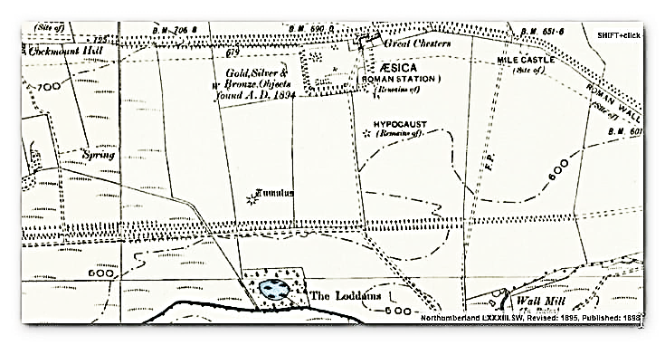
This 1800s map shows the Great Chesters Fort (Aesica) and the bath house south of the Fort – it also indicates a path for an Aqueduct going south to the Vallum and then to the river. This shows the water travelling downhill from 208m high at the Fort to 180m at the river – this is the OUTLET of the water.
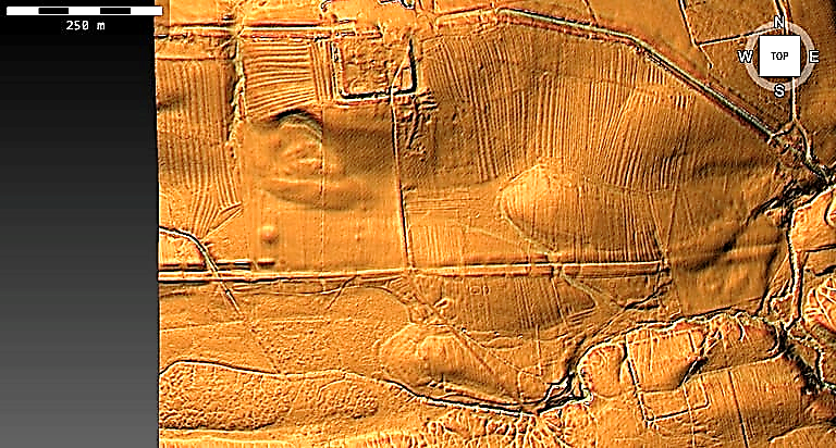
The Lidar map shows this much better but moreover, it also indicates that the outlet is NOT the river but the Vallum.
So, is the Great Chesters Aqueduct (all 9km) connected to this point in the Fort?
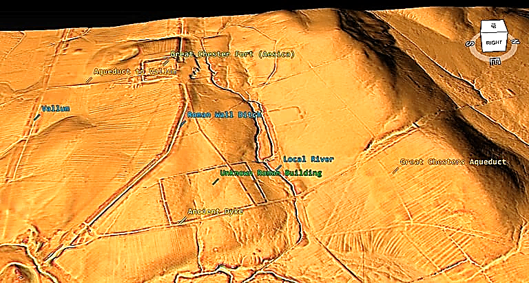
The Great Chesters Aqueduct is too far from the fort to connect, and there is no sign of anything on Lidar. LiDAR suggests that a Dyke connects the local river to the Wall Ditch and that the Wall ditch is so deep it is below the water table, making it a moat.
Looking at the other side of this ditch/moat, we see a break in the wall that may have allowed water to feed the moat/ditch via another ancient dyke?
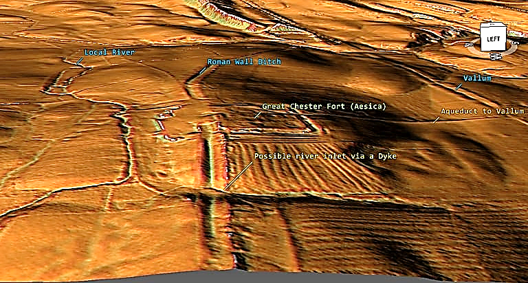
This connection seems to agree with excavations of Aesica, which show the ‘aqueduct’ going through the centre of the fort.
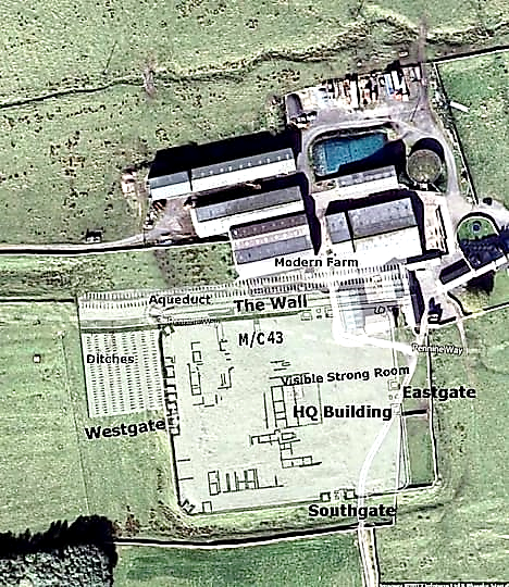
If the Great Chesters Aqueduct is not a 9km Roman piece of engineering – what do we see in the Landscape?
LiDAR Investigation starting North East of the Fort – Section One
We will look at each section, in turn, to see if it existed and whether it would flow as expected or has another more feasible explanation. The start of the Aqueduct, which we will call section 1, is by the River Caw Burn (which flows from Right to Left) and flows the river for a while (Fig. 1 – top right corner) without reason or any ditch found on LiDAR.
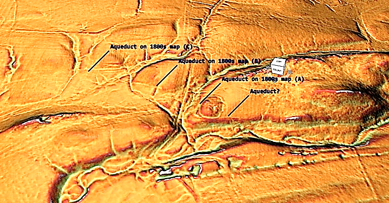
Connecting to the river before (C) in the suggested route would not make much sense as the river runs alongside, and it would need to fight against gravity (section C is two metres higher than A). However, it could connect up better to section (A) via the stream running past section (A) to the right much more effectively (unless it was dry during this period).
What is more interesting and missed by the archaeologists is the artificial Dyke that cuts North-South between Sections B and C connecting the stream to the river with banks on both sides – the southern half is now dry and used as a footpath, but LiDAR clearly shows at one time it went directly from the prehistoric stream.
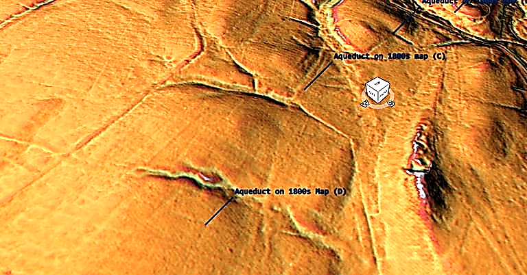
Section two shows that the Aqueduct goes from 4m wide in (C) to 1m wide in (D) over a minimal length. Moreover, again LiDAR suggests that at (C), this 4m ditch connects to another Paleochannel (that would have held water in prehistory) and then seems to head South of (D) to get another paleochannel keeping the 4m width.
Section 3 goes on a ‘merry dance’ around the landscape without good evidence or reason. The OS map suggests that the route south then north is not required as you could just continue on the same line, confirmed on the LiDAR map.
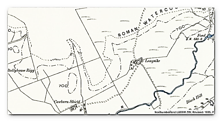
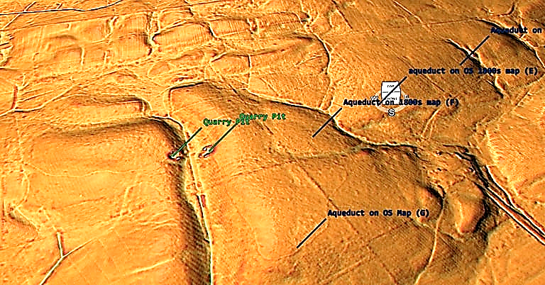
Closure inspection would suggest that (E) terminates in the Paleochannel and (F) is a linear feature that continues past the paleochannel and does not connect to the suggested aqueduct.
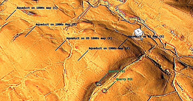
Section 4 shows that the aqueduct stops at the quarry and starts again on the quarry opposite and does not go around or through the valley as suggested on the OS maps – but what it does open up is the possibility that a stone bridge once connected the aqueduct which has been robbed out?? as it is 50m wide and of the same altitude with a slight slope right to left.
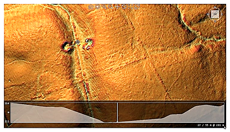
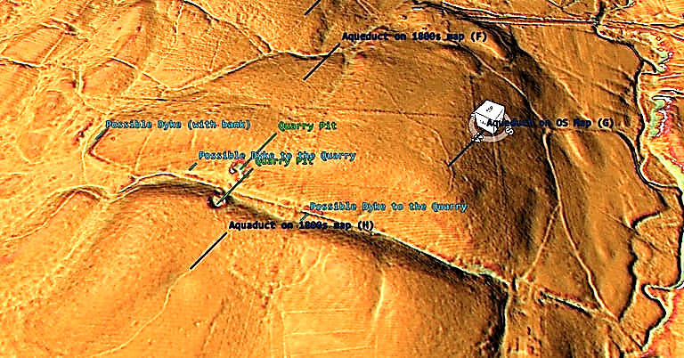
If the quarry pits are not the foundations of a stone bridge – then these quarry pits do seem to have Dykes connecting them to the paleochannel. What there is not is a continuation of the Aqueduct north of each pit. The ditch on section (H) is again quite pronounced at 2m in width – which is more than adequate for ample water is somewhat overkill as some regions are only 1m wide and so is wasted over-engineering.
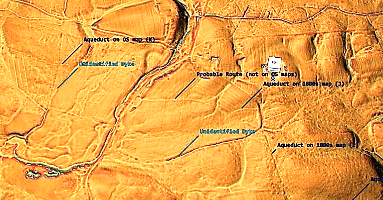
The aqueduct in the area (J) seems to connect to another unidentified Dyke of much larger specification (8m wide with Bank) before turning West and, on the OS map moving north to the settlement of Edges Green and crossing the river (via a bridge??), but LiDAR sees no evidence of this suggested route. However, we do see (but missed by archaeologists) that the course goes west to the paleochannel, only to reappear out of another Paleochannel to the West (K).
Moreover, the LiDAR map shows two more possible Dykes – the one on the East side, 8m in width with a 4m ditch and bank and the one on the East, 10m wide with a 5m bank and ditch.
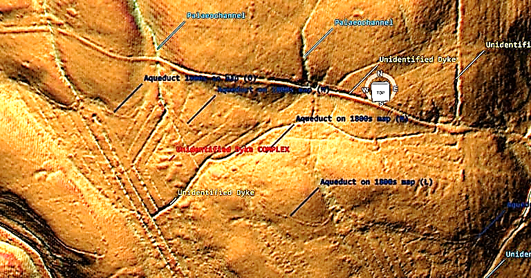
In section 6, the aqueduct can be better seen but of limited size in width (one metre) – what we do see in Section 6 shows a water complex of unknown date but links into other linear earthworks (Dykes) not recognised or scheduled currently. This ‘diamond complex may be the first sign of agriculture in the area using the existing Dyke canals as a water source for farming crops. Each of these sections are 11m (33ft) wide and would have access to water 365 days a year.
We are now left with two tantalising possibilities as these complex cuts through the aqueduct. First, if the aqueduct is ROMAN, then the complex is later in history (selion is a medieval open strip of land or a small field used for growing crops, usually owned by or rented to peasants.
A selion of land was typically one furlong (660 ft) long and one chain (66 ft) wide, so one acre in the area?) – which means that water levels (as the paleochannels needed to be full of water to work) were much higher in the past (Roman Period) than currently accepted.
OR is the aqueduct much older than the experts suggest by thousands of years?
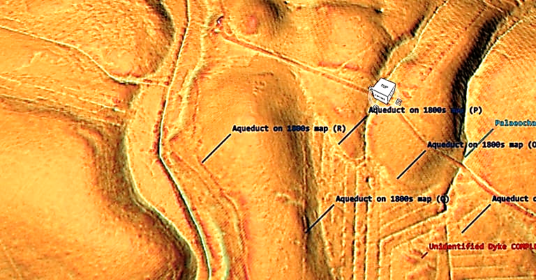
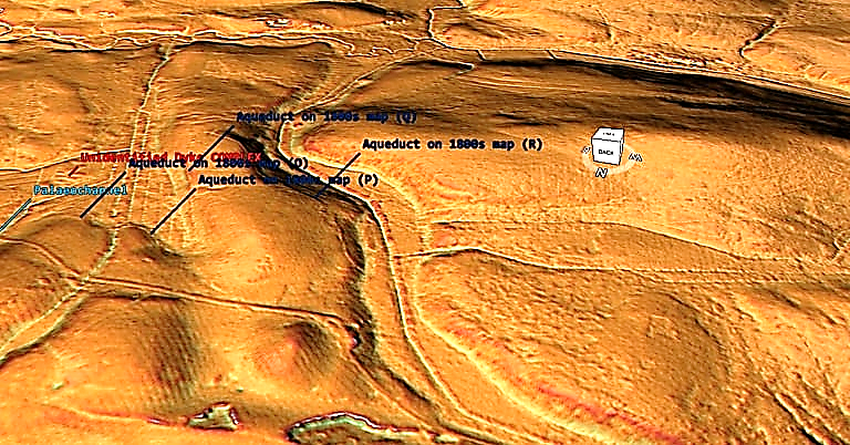
The aqueduct in section seven (for a second time) takes a detour South, then north around a shallow mound. The NW view shows that this path could have been halved by going around the north section of the mound – so why the extra work?
Moreover, although the OS maps (and Historic England Scheduled Maps) show that the aqueduct crosses the river (authors suggesting a wooden bridge at this point), unlike the previous bridge section showing two pits on either side of the river, LiDAR shows no structure and no continuation on the opposite bank – so was this the end?
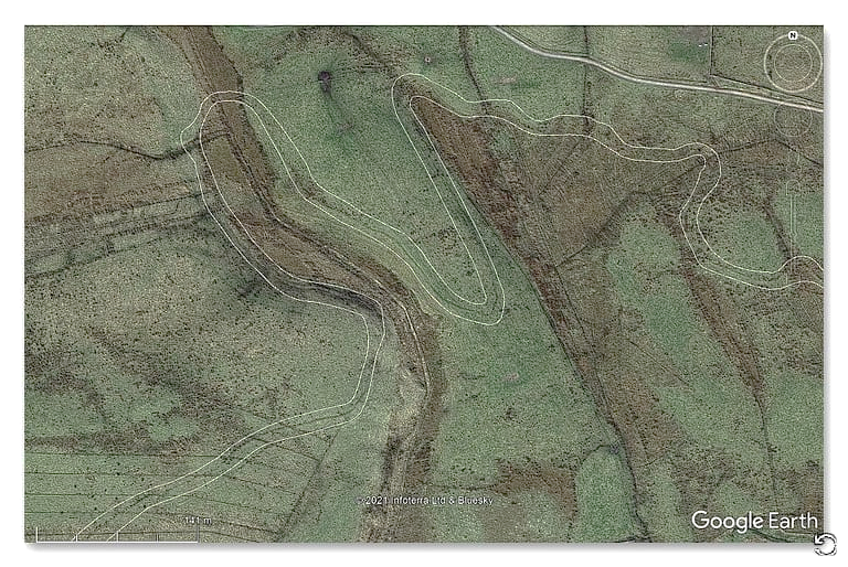
This missing section and bridge is compounded when you look at the GE satellite map as you wonder if you wanted to cross the river, why go so far north when you could have crossed in the south, saving time and labour?
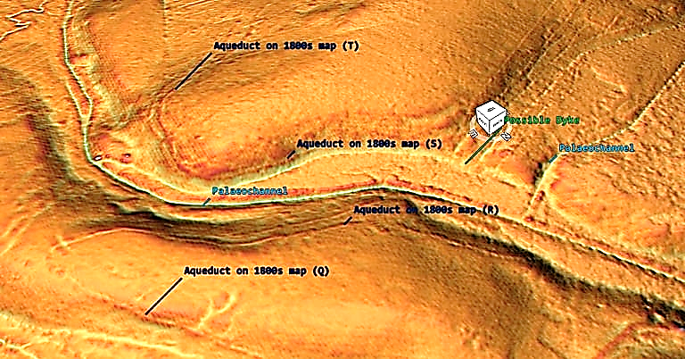
Section 8 shows that the aqueduct seems to come out of a possible Dyke – if the OS maps are correct and the dyke is part of the aqueduct, how does a 4m wide ditch reduce to a metre. Moreover, why does the Dyke continue and connects to a paleochannel later downstream whilst the aqueduct turns (as if it draws water from the Dyke) and continues in a very different direction?
It should also be noted that the paleochannels in this section (right) seem to have banks which would suggest they were used as Dykes?
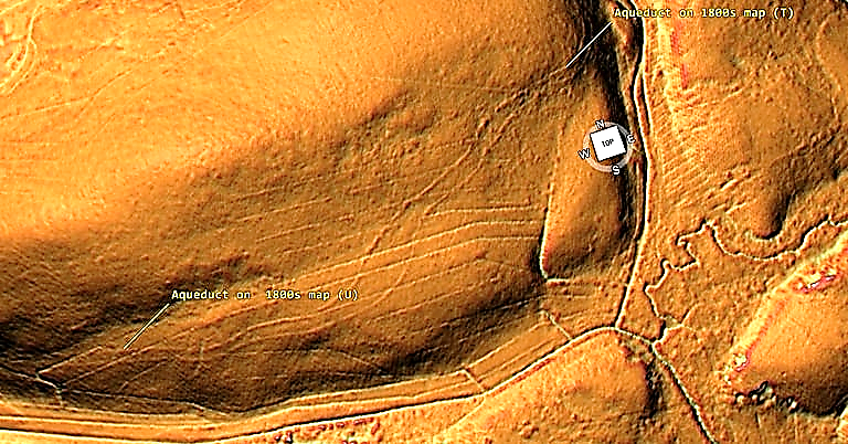
Section 9 is fascinating as it turns from one Aqueduct into two (again, which has not been recognised by the archaeologists.
The question is “why two”?
Was there so much water that one channel could not cope – if so, why not just widen the ditch as we have seen in other sections? Did one of the ditches dry up, and so another was dug – if so, then the experts underestimated the groundwater more than the water flow. Indeed, both ditches enter a depression in the landscape (quarry?) by ‘Benks Bridge’, and there is no sign of it crossing the bridge.
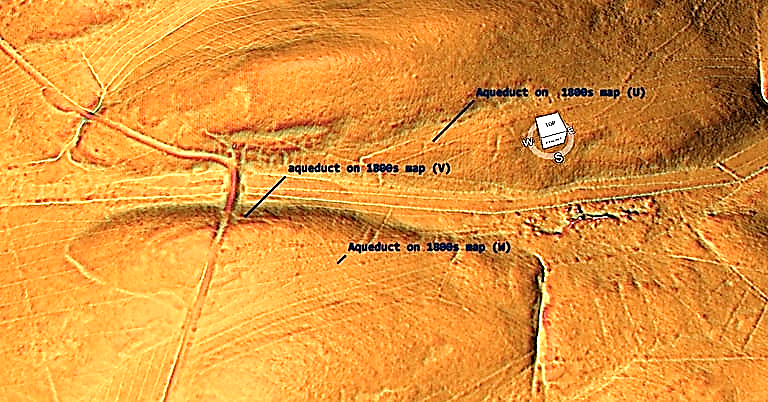
Section 10 shows a much shallower ditch than seen in the north heading from the bridge (W) towards a paleochannel, which turns south then north to avoid the gradient (X).
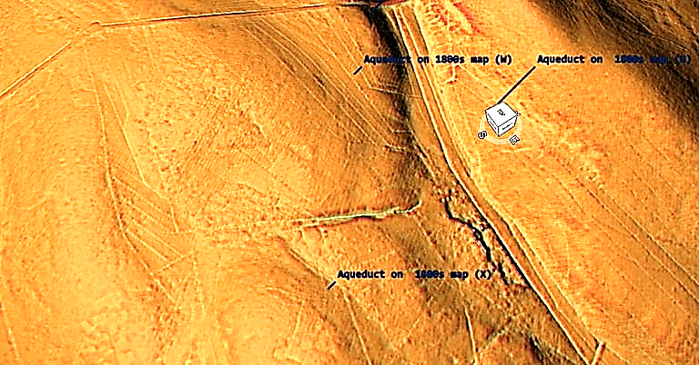
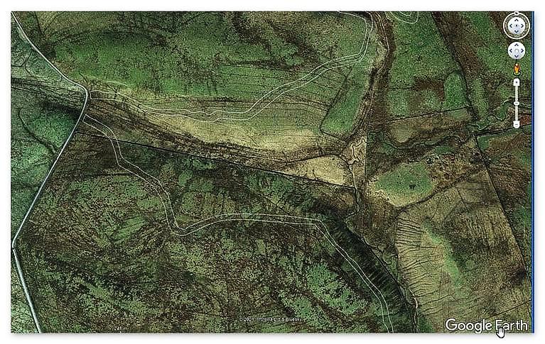
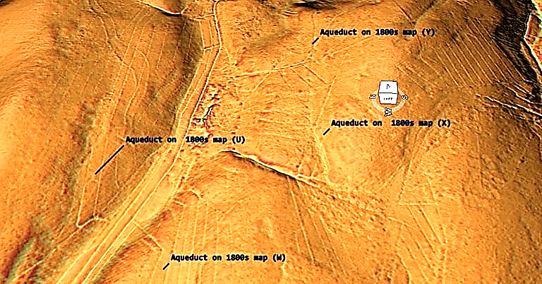
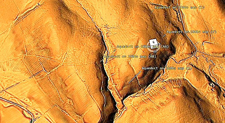
The ditch now moves east and becomes more obvious (Y).
The Aqueduct (Z) to (AA) now follows the contours of the landscape around a dry river valley (Paleochannel) before coming back on itself again, where archaeologists suspect it crosses the valley via an unidentified bridge.
The LiDAR map suggests it disappears into the river valley, and the opposite route of the Aqueduct originates at a different location.
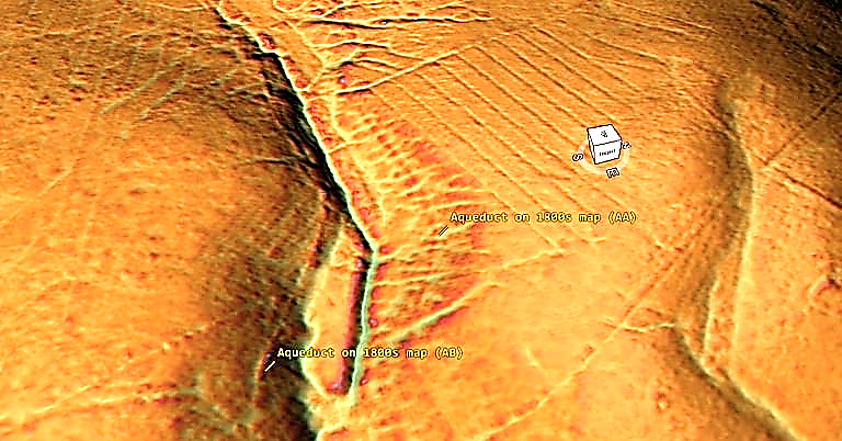
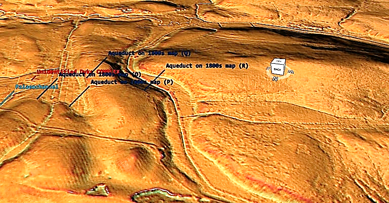
Moreover, on the southern side of the Paleochannel the size of the Aqueduct increases significantly. On the northern side, it is 1 – 2m in width, and on the Southern side, it is now 12m with a 6m ditch and bank.
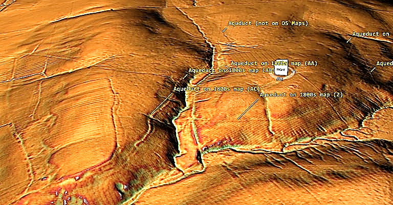
What we care about seeing is an independent Dyke which goes from Paleochannel to Paleochannel and has been misidentified by archaeologists attempting to rationalise this strange ditch/aqueduct.
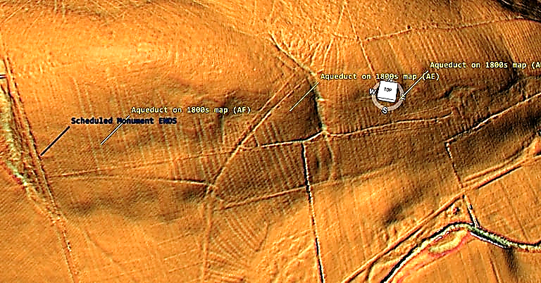
The last leg of this Aqueduct returns again to a shallow 1m width channel that joins the more extensive 12m ditch system on the bend of the landscape – which we have found no clear evidence for such an assumption. At this point, the Scheduling for the monument ends, entering another Paleochannel.
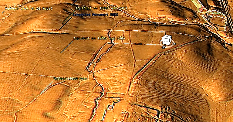
The last leg of the Aqueduct (according to the 1800s OS maps) takes the aqueduct to the Great Chesters Fort (Aesica) – but the LiDAR map shows that the ditch falls short (300m) and disappears in a river north of the fort.
Conclusion
It is clear from the LiDAR research that the suspected Roman Aqueduct is not as it seems. This is not the first examination to spread doubt about the scale and origin of this feature in the landscape – MacKay, D. A. (1990). The Great Chesters Aqueduct: A New Survey. Britannia, 21, 285–289. Also shows an incomplete map of this aqueduct.

Mackey failed to find in their survey that the Aqueduct changed size, and the path suggested had no identifiable remains of the bridges required to make this Aqueduct work.
Our more detailed findings indicate that the topology of the aqueduct (Fig.1) suggests that it would need to go uphill at several points without any powered assistance (like a siphon) and so is mechanically unsound. Our finding has found that the use of ‘Dykes’ in this area and some connecting to this Aqueduct feature is new. We have also shown that closer to the Fort it was supposed to supply, there were closed water sources which could be used and that the Fosse by the Wall was also a water supply. Moreover, the most straightforward collection of available water that historians and Archaeologists have wholly ignored is a WELL!! Wells were used all over Roman Britain, and it is clear from the Paleochannels in this area that a well of just 30 – 40 would have tapped sufficient water for both the Fort and baths.
We conclude that we found a prehistoric watercourse linked to their sophisticated ‘Dyke’ system. I would be bold to suggest that this was used for either agricultural purposes or maybe industrial, seeing the multiple sites of quarries associated and in the region of this feature.

This was an extracts from the NEW Book Ancient Prehistoric Canals (Dykes) – Wansdyke available on Amazon as a FULL COLOUR HARD BACK (£49.95) or a ECONOMY (£9.99) SOFTBACK black and white VERSION – it is also available as a KINDLE (£2.99) book. For further information about our work on Prehistoric Britain visit our WEBSITE or VIDEO CHANNEL.
Product details
- ASIN : B0BN7PD6BS
- Publisher : Independently published (24 Nov. 2022)
- Language : English
- Hardcover : 477 pages
- ISBN-13 : 979-8358524187
- Dimensions : 15.24 x 3.33 x 22.86 cm
- Illustrations: 350+
For more information about British Prehistory and other articles/books, go to our BLOG WEBSITE for daily updates or our VIDEO CHANNEL for interactive media and documentaries. The TRILOGY of books that ‘changed history’ can be found with chapter extracts at DAWN OF THE LOST CIVILISATION, THE STONEHENGE ENIGMA and THE POST-GLACIAL FLOODING HYPOTHESIS. Other associated books are also available such as 13 THINGS THAT DON’T MAKE SENSE IN HISTORY and other ‘short’ budget priced books can be found on our AUTHOR SITE or on our PRESS RELEASE PAGE. For active discussion on the findings of the TRILOGY and recent LiDAR investigations that is published on our WEBSITE you can join our FACEBOOK GROUP.

