Great Chesters (Roman) Aqueduct (Part Two)
This is PART TWO of Great Chesters (Roman) Aqueduct LiDAR survey – Part One is available HERE. NB. the flick book version has enhanced colour hi-res zoom illustrations for studying purposes.
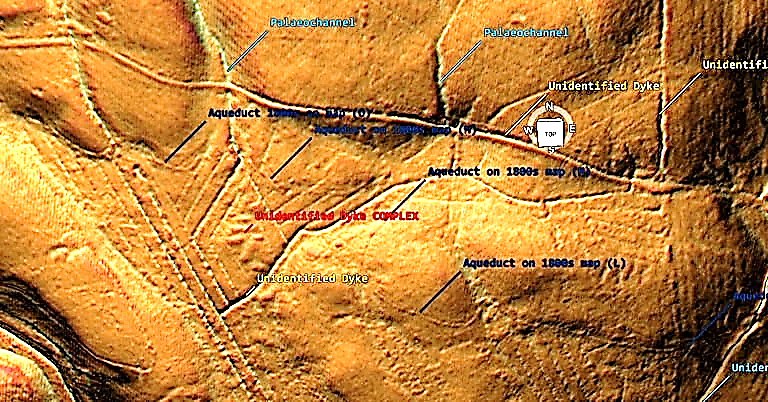
On section 6 the aqueduct can be better seen but of limited size in width (one metre) – what we do see in Section 6 is a water complex of unknown date but clearly linking into other linear earthworks (Dykes) not recognised or scheduled currently. This ‘diamond complex maybe the first signs of agriculture in the area using the existing Dyke canals as a water source for farming crops. Each of these section are 11m (33ft) wide and would have access to water 365 days a year.
We are now left with two tantalising possibilities as this complex cuts through the aqueduct. If the aqueduct is ROMAN then the complex is later in history (selion is a medieval open strip of land or a small field used for growing crops, usually owned by or rented to peasants. A selion of land was typically one furlong (660 ft) long and one chain (66 ft) wide, so one acre in area?) – which means that water levels (as the palaeochannels needed to be full of water to work) were much higher in the past (Roman Period) than currently accepted?
OR the aqueduct is much older than the experts suggest by thousands of years?
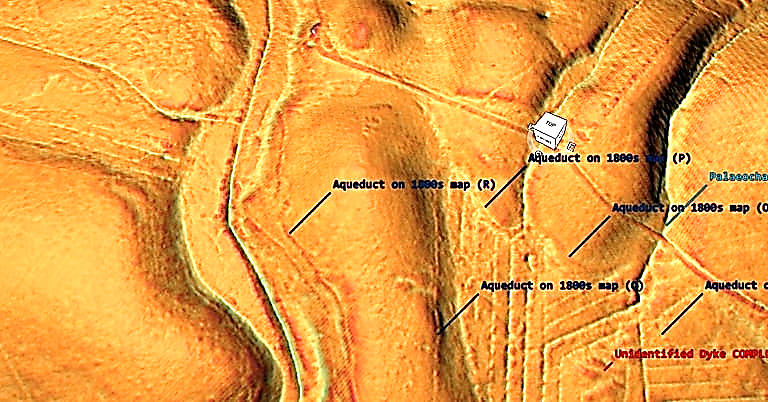
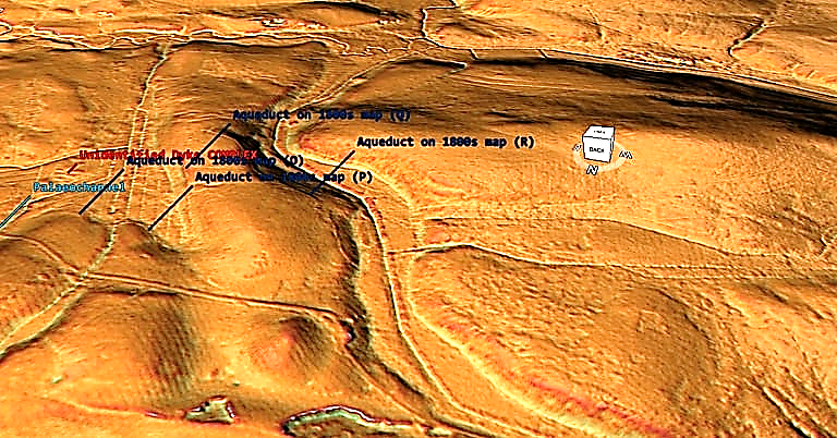
The aqueduct in section seven (for a second time) takes a detour South then north around a shallow mound. The NW view shows that this path could have been halved by going around the north section of the mound – so why the extra work? Moreover, although the OS maps (and Historic England Scheduled Maps) show that the aqueduct crosses the river (authors suggesting a wooden bridge at this point) but unlike previous bridge section showing two pits either side of the river, LiDAR shows no structure and no continuation on the opposite bank – so was this the end?
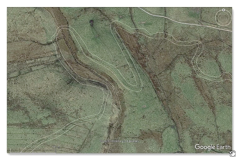
This missing section and bridge is compounded when you look at the GE satellite map as you wounder if you wanted to cross the river, why go so far north when you could have crossed in the south saving time and labour?
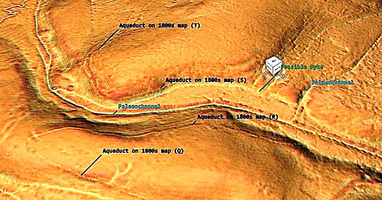
Section 8 shows that the aqueduct seems to come out of a possible Dyke – if the OS maps are correct and the dyke is part of the aqueduct then hows does a 4m wide ditch reduce to a metre. Moreover, why does the Dyke continue and connects to a palaeochannel later down stream whilst the aqueduct turns (as if it draws water from the Dyke) and continues in a very different direction?
It should also be noted that the palaeochannels in this section (right) seem to have banks which would suggest they were used as Dykes?
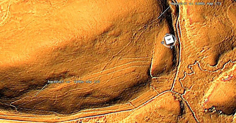
Section 9 is very interesting as it turns from one Aqueduct into two (again which has not been recognise by the archaeologists.
The question is “why two”?
Was there so much water that one channel could not cope – if so why not just widen the ditch as we have seen in other sections? Did one of the ditches dry up and so another was dug – if so then the groundwater more than the waterflow has been underestimated by the experts? What is sure is that both ditches end entering a depression in the landscape (quarry?) by ‘Benks Bridge’ and there is no sign of it crossing the bridge.
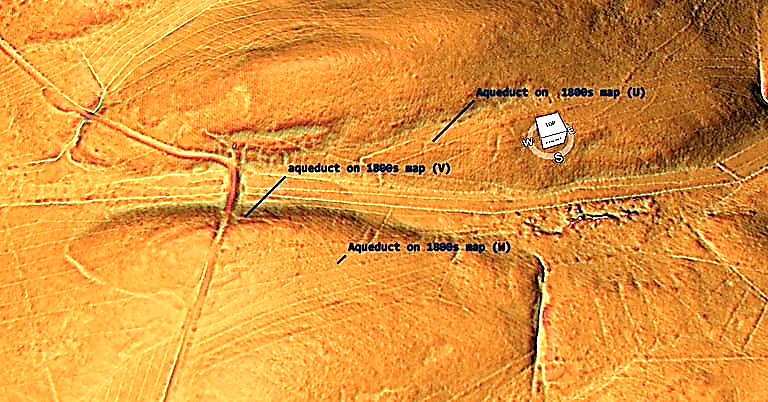
Section 10 shows a much shallower ditch than seen in the north heading from the bridge (W) towards a palaeochannel, where is turns south then north to avoid the gradient (X).
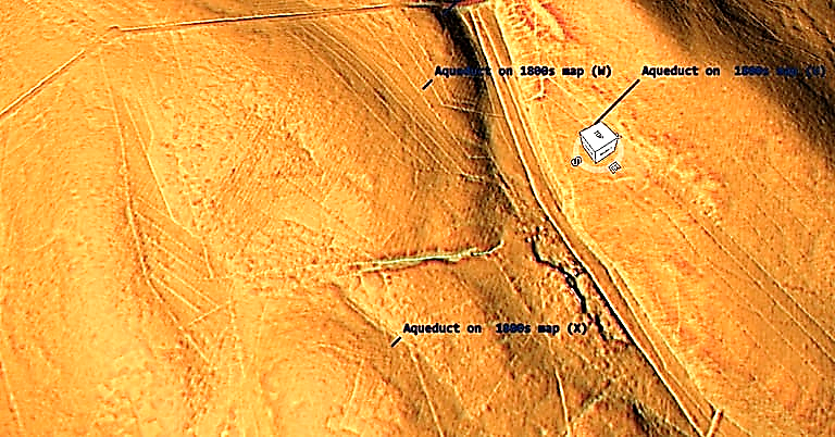
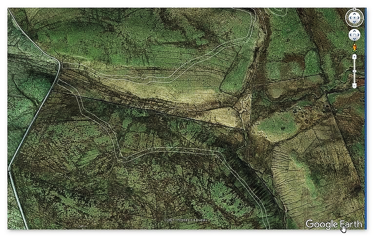
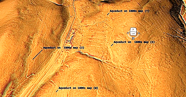
The ditch now moves east and become s more obvious (Y).
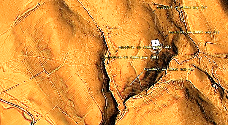
The Aqueduct (Z) to (AA) now follows the contours of the landscape around a dry river valley (Palaeochannel) before coming back on itself again, where archaeologists suspect it cross the valley via an unidentified bridge.
The LiDAR map suggest it disappears into the river valley and the opposite route of the Aqueduct originates at a different location.
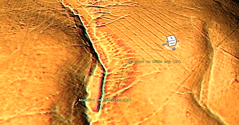
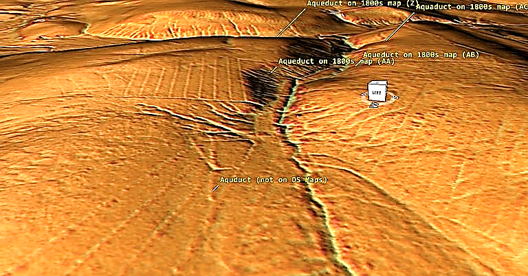
Moreover, on the southern side of the Palaeochannel the size of the Aqueduct increases significantly. On the northern side it is 1 – 2m in width and on the Southern side it is now 12m with a 6m ditch and bank.
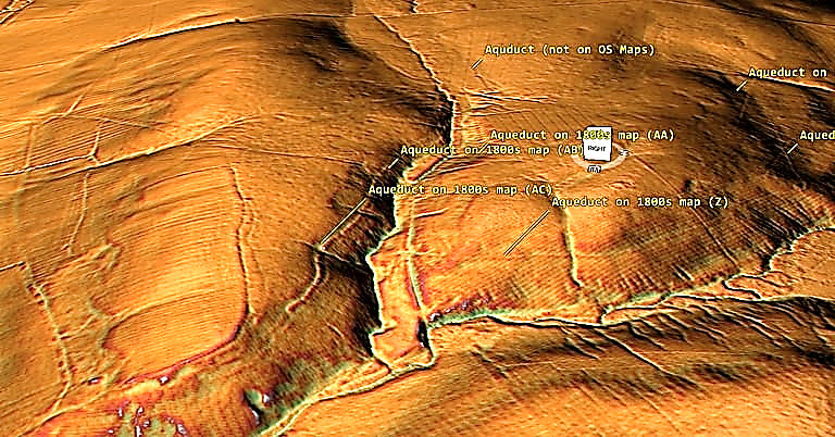
What we care seeing is an independant Dyke which goes from Palaeochannel to Palaeochannel and has been misidentified by archaeologists attempting to rationalise this strange ditch/aqueduct.
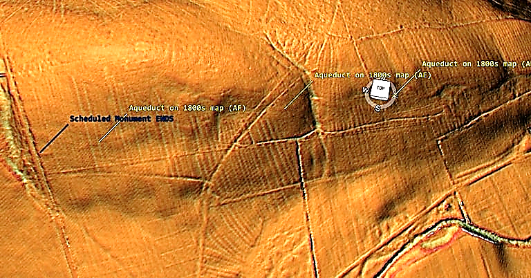
The last leg of this Aqueduct returns again to a shallow 1m width channel that apparently joins the larger 12m ditch system on the bend of the landscape – which we have found no clear evidence for such an assumption. At this point the Scheduling for the monument ends entering another Palaeochannel.
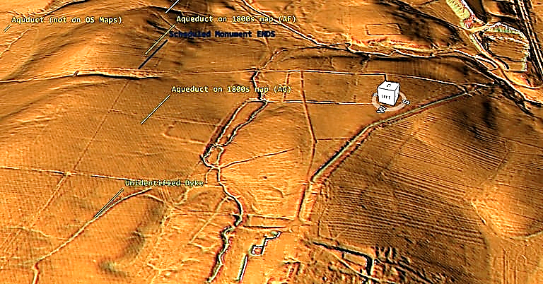
The last leg of the Aquaduct (according to the 1800s OS maps) takes the aqueduct to the Great Chesters Fort (Aesica) – but the LiDAR map shows that the ditch falls short (300m) and disappears in a river north of the fort.
Conclusion
It is clear that from the LiDAR research that the suspected Roman Aqueduct is not as it seems. This is not the first examination to spread doubt about the scale and origin of this feature in the landscape – MacKay, D. A. (1990). The Great Chesters Aqueduct: A New Survey. Britannia, 21, 285–289. Also shows an incomplete map of this aqueduct.
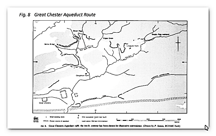
What Mackey failed to find in their survey is that the Aqueduct changes size and the path suggested had no identifiable remains of the bridges required to make this Aqueduct work.
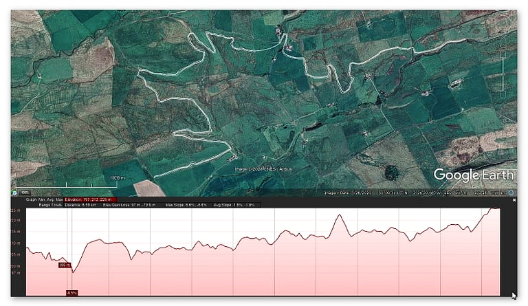
Our more detailed findings indicate that the topology of the aqueduct (Fig.1) indicates that it would need to go up hill at several points without any powered assistance (like a siphon) and so is mechanically unsound. What our finding have found that is new is the use of ‘Dykes’ in this area and some connecting to this Aqueduct feature. We have also shown that closer to the Fort it was supposed to supply there was closure water sources which could be used and that the Fosse by the Wall was also a water supply. Moreover, the easiest supply of water which was available and has been completely ignored by historians and Archaeologists is a WELL!! Wells were used all over Roman Britain and it is clear from the Palaeochannels in this area that a well of just 30 – 40 would have tapped sufficient water fro both the Fort and baths?
Our conclusion is that this what we have found is a prehistoric watercourse that was linked to their very sophisticated ‘Dyke’ system. I would be bold to suggest that this was used for either agricultural purposes or mybe industrial seeing the multiple sites of quarries associated and in the region of this feature.
For more information about Linear Earthworks (Dykes) see our other BLOG POSTS or our LiDAR Investigations on our YOUTUBE channel – Great Chesters (Roman) Aqueduct.
Further Reading
For information about British Prehistory, visit www.prehistoric-britain.co.uk for the most extensive archaeology blogs and investigations collection, including modern LiDAR reports. This site also includes extracts and articles from the Robert John Langdon Trilogy about Britain in the Prehistoric period, including titles such as The Stonehenge Enigma, Dawn of the Lost Civilisation and the ultimate proof of Post Glacial Flooding and the landscape we see today.
Robert John Langdon has also created a YouTube web channel with over 100 investigations and video documentaries to support his classic trilogy (Prehistoric Britain). He has also released a collection of strange coincidences that he calls ‘13 Things that Don’t Make Sense in History’ and his recent discovery of a lost Stone Avenue at Avebury in Wiltshire called ‘Silbury Avenue – the Lost Stone Avenue’.
Langdon has also produced a series of ‘shorts’, which are extracts from his main body of books:
For active discussions on the findings of the TRILOGY and recent LiDAR investigations that are published on our WEBSITE, you can join our and leave a message or join the debate on our Facebook Group.


Pingback: Great Chesters (Roman) Aqueduct - Debunked (Part One) - Prehistoric Britain
Pingback: Section K - NY76NW - Prehistoric Britain